Adafruit QT Py ESP32 Pico
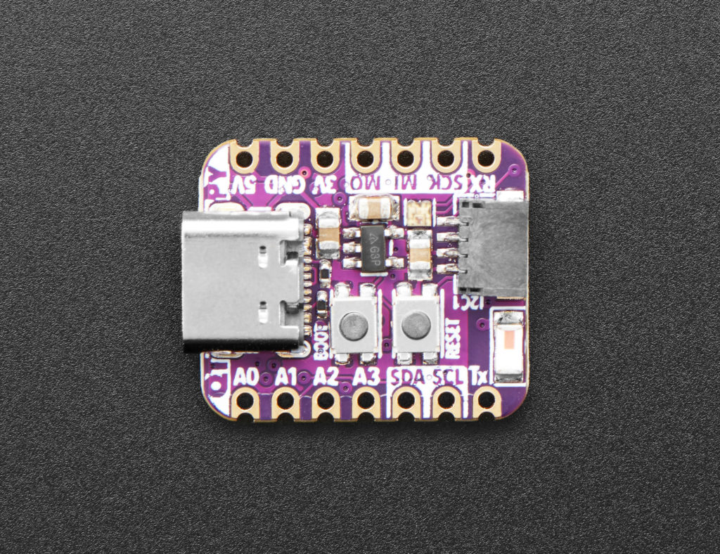
The QT Py ESP32 Pico is a small microcontroller board with Wi-Fi and Bluetooth connectivity. The heart of the board is the all-in-one ESP32 Pico V3 02. This chip provides 2.4 GHz Wi-Fi and Bluetooth (with BLE). It has 8 MB of flash memory and 2 MB of RAM. It even brings its own oscillator. Adafruit adds to that a USB bridge for programming via the USB-C connector, a chip antenna, and a NeoPixel RGB LED for status indication. Adafruit also broke two pins to a STEMMA QT connector for connecting I2C-based IO devices. STEMMA QT is compatible with Sparkfun's QWIIC.
The form factor of the ESP32 Pico matches that of the Seeed Studio XIAO cards. Fourteen pins are divided into headers. There are slots with the header pins, but note that there are chips on both sides of the board, so it can't be flush mounted to a larger board without a cutout for chips. As this is a double sided board, be sure to choose the direction before soldering the headers.
 Same size as Seeed Studio XIAO series!
Despite the small number of pins, the broken ones perform very well. Three pins are reserved for power connections. Four pins are labeled as analog inputs, but actually ten of the eleven GPIO pins accept 12-bit analog input. Two of the analog pins also act as 8-bit DAC outputs. Three pins are marked for SPI hardware communication, two pins for I2C, and two for serial UART. All pins are capable of PWM output. The two header pins marked for I2C are separate from the two I2C pins on the STEMMA QT connector, so a total of thirteen GPIO pins are spread out. The NeoPixel RGB LED is on its own microcontroller pin, so it doesn't conflict with any other I/O pins.
All I/O on the QT Py ESP32 Pico is 3.3V. There is a 3.3V regulator on board which provides up to 600mA "peak" but probably shouldn't be tested near its limit. There is a 5V pin on the board which provides power from the USB connector, which means 5V is not available when not connected to USB. There are two pads on the bottom of the board labeled "VBat" which provide a diode protected place to connect a battery. You can also power the board through the 5V pin, but Adafruit warns you to supply your own diode to protect the battery when the board is connected to USB.

The QT Py ESP32 Pico is a small microcontroller board with Wi-Fi and Bluetooth connectivity. The heart of the board is the all-in-one ESP32 Pico V3 02. This chip provides 2.4 GHz Wi-Fi and Bluetooth (with BLE). It has 8 MB of flash memory and 2 MB of RAM. It even brings its own oscillator. Adafruit adds to that a USB bridge for programming via the USB-C connector, a chip antenna, and a NeoPixel RGB LED for status indication. Adafruit also broke two pins to a STEMMA QT connector for connecting I2C-based IO devices. STEMMA QT is compatible with Sparkfun's QWIIC.
The form factor of the ESP32 Pico matches that of the Seeed Studio XIAO cards. Fourteen pins are divided into headers. There are slots with the header pins, but note that there are chips on both sides of the board, so it can't be flush mounted to a larger board without a cutout for chips. As this is a double sided board, be sure to choose the direction before soldering the headers.
Same size as Seeed Studio XIAO series!
Despite the small number of pins, the broken ones perform very well. Three pins are reserved for power connections. Four pins are labeled as analog inputs, but actually ten of the eleven GPIO pins accept 12-bit analog input. Two of the analog pins also act as 8-bit DAC outputs. Three pins are marked for SPI hardware communication, two pins for I2C, and two for serial UART. All pins are capable of PWM output. The two header pins marked for I2C are separate from the two I2C pins on the STEMMA QT connector, so a total of thirteen GPIO pins are spread out. The NeoPixel RGB LED is on its own microcontroller pin, so it doesn't conflict with any other I/O pins.
All I/O on the QT Py ESP32 Pico is 3.3V. There is a 3.3V regulator on board which provides up to 600mA "peak" but probably shouldn't be tested near its limit. There is a 5V pin on the board which provides power from the USB connector, which means 5V is not available when not connected to USB. There are two pads on the bottom of the board labeled "VBat" which provide a diode protected place to connect a battery. You can also power the board through the 5V pin, but Adafruit warns you to supply your own diode to protect the battery when the board is connected to USB.
What's Your Reaction?