Bare-Metal STM32: Configuring and Using SPI
The Serial Peripheral Interface (SPI) was originally standardized by Motorola in 1979 for short-range communication in embedded systems. In its most common four-wire configuration, full-duplex data transfer is possible on both data lines (MOSI, MISO) with data rates well in excess of 10 Mb/s. This makes SPI suitable for high-bandwidth applications full-duplex such as SD storage cards and high-resolution, high-refresh displays.
STM32 devices come with a varying number of SPI devices, two in the F042 at 18 Mb/s and five in the F411. Across all STM32 families, the SPI device is relatively similar, with fairly minor differences in register layout. In this article, we will see how to configure an SPI device in master mode.
Define the SPIAn interesting and perhaps annoying fact with SPI is that while it can support multiple devices, it has no address bus, but instead requires a designated pin to be pulled low on the device, usually referred to as Slave Select (SS) or Chip Select (CS). With SS high, the slave device puts its other pins into high impedance mode, effectively disconnecting from the SPI lines. STM32 SPI devices have a provision for a dedicated SS pin (NSS) which can streamline this process if only one device is connected. Typically you want to use GPIO pins to toggle these SS pins, with one GPIO pin per device.
For four-wire SPI, the master and slave devices are therefore connected with the following lines, with the SS line duplicated for each additional slave:
SCLK (serial clock, from master) MOSI (master output, slave input) MISO (master input, slave output) SS (slave selection)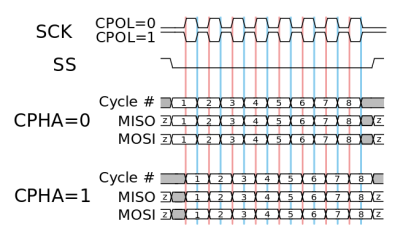 SPI timing diagram, showing the different CPHA and CPOL configurations.
Configuring the SPI device is relatively simple, requiring configuration of the clock and parameters such as 8 or 16 bit transfers. Less obvious are the SPI clock polarity (CPOL) and phase (CPHA) settings. Here the default (mode 0) is usually CPOL 0 and CPHA 0, which results in a slow clock line and new data pushed onto the data line on the trailing edge of the current clock cycle . CPOL 1 and CPHA 1 cause the opposite behavior. Slaves may support modes other than Mode 0, but each slave's datasheet should be consulted on a case-by-case basis.
Thanks to all this, we can consider configuring SPI on the F411 and F042 microcontrollers. Due to the aforementioned similarity between the SPI devices of the STM32 families, it is relatively simple to adapt the initialization routine. The data transfer routines themselves remain unchanged.
Set things upConfiguring an SPI master starts with the configuration of the GPIO pins that we will be using. This involves setting the Alternate Function (AF) mode and appropriate pin settings, for example AF5 on pins 4-6 of the F411 microcontroller on port A. The SPI pins themselves are assigned the following properties: /p> SCLK: floating, push-pull, high speed. MOSI: floating, push-pull, high speed. MISO: pull-up, push-pull, high speed. SS: pull-up, push-pull, high speed.
If...
The Serial Peripheral Interface (SPI) was originally standardized by Motorola in 1979 for short-range communication in embedded systems. In its most common four-wire configuration, full-duplex data transfer is possible on both data lines (MOSI, MISO) with data rates well in excess of 10 Mb/s. This makes SPI suitable for high-bandwidth applications full-duplex such as SD storage cards and high-resolution, high-refresh displays.
STM32 devices come with a varying number of SPI devices, two in the F042 at 18 Mb/s and five in the F411. Across all STM32 families, the SPI device is relatively similar, with fairly minor differences in register layout. In this article, we will see how to configure an SPI device in master mode.
Define the SPIAn interesting and perhaps annoying fact with SPI is that while it can support multiple devices, it has no address bus, but instead requires a designated pin to be pulled low on the device, usually referred to as Slave Select (SS) or Chip Select (CS). With SS high, the slave device puts its other pins into high impedance mode, effectively disconnecting from the SPI lines. STM32 SPI devices have a provision for a dedicated SS pin (NSS) which can streamline this process if only one device is connected. Typically you want to use GPIO pins to toggle these SS pins, with one GPIO pin per device.
For four-wire SPI, the master and slave devices are therefore connected with the following lines, with the SS line duplicated for each additional slave:
SCLK (serial clock, from master) MOSI (master output, slave input) MISO (master input, slave output) SS (slave selection)
SPI timing diagram, showing the different CPHA and CPOL configurations.Configuring the SPI device is relatively simple, requiring configuration of the clock and parameters such as 8 or 16 bit transfers. Less obvious are the SPI clock polarity (CPOL) and phase (CPHA) settings. Here the default (mode 0) is usually CPOL 0 and CPHA 0, which results in a slow clock line and new data pushed onto the data line on the trailing edge of the current clock cycle . CPOL 1 and CPHA 1 cause the opposite behavior. Slaves may support modes other than Mode 0, but each slave's datasheet should be consulted on a case-by-case basis.
Thanks to all this, we can consider configuring SPI on the F411 and F042 microcontrollers. Due to the aforementioned similarity between the SPI devices of the STM32 families, it is relatively simple to adapt the initialization routine. The data transfer routines themselves remain unchanged.
Set things upConfiguring an SPI master starts with the configuration of the GPIO pins that we will be using. This involves setting the Alternate Function (AF) mode and appropriate pin settings, for example AF5 on pins 4-6 of the F411 microcontroller on port A. The SPI pins themselves are assigned the following properties: /p> SCLK: floating, push-pull, high speed. MOSI: floating, push-pull, high speed. MISO: pull-up, push-pull, high speed. SS: pull-up, push-pull, high speed.
If...
What's Your Reaction?